Building, restoration, and repair with epoxy


How to Build Rudders & Centerboards
by Captain James R. Watson
When the centerboard of my Searunner trimaran broke in the middle of a windy race around the Black Hole, the question I kept asking was “Why now, after working fine all of this time, and when we were leading the race?”
“Guess it just wore out” was my excuse to myself. This centerboard was built of laminated layers of plywood, resulting in a thickness of 2″. It was then covered with two layers of 6-oz woven fiberglass fabric. It was a deep and wide board with a lot of area, and like any rudder or centerboard on a boat that is sailed hard, it was exposed to a fair amount of stress.
The answer to “Why now – while leading the race?” could have been fate. But there is a more scientific answer. Extensive laboratory testing at Gougeon Brothers, Inc. defines why the centerboard failed. Understanding why can help us design and construct components that will perform more efficiently and last much longer.
The plywood centerboard did, in fact, wear out – or more accurately – it failed from rolling shear fatigue. Fatigue cracks in a material result from repeated (cyclic) stress. Fatigue is a reality of all structures and materials and eventually culminates in structural failure. Repeated loading and unloading or even worse, loading one way and then the other (reverse axial), rapidly reduces a material’s physical integrity and accelerates degradation. The higher the load is as a percentage of the material’s ultimate strength, the more rapid is the deterioration.
Some materials have a greater fatigue life than others. Ounce per ounce, wood is capable of operating at a much higher percentage of its ultimate stress level than most other materials. That is why such wonderfully efficient structures can be built with wood. However, plywood is not a good choice for cantilevered structures such as rudder blades and centerboards. This is because plywood is susceptible to rolling shear, shearing forces that roll the structural fibers across the grain. Plywood’s unidirectional wood fibers are laid in alternating layers, approximately half of them are oriented 90 degrees to the axis of the loads. Like a bundle of soda straws, which resist bending moments quite well one way, they simply lack cross-grain strength laterally and can roll against one another and fail under relatively low stress, especially in a cyclic environment. Therefore, when anticipated loads are primarily unidirectional, it is ideal to use a material with good unidirectional strength. Since only half of the plywood’s wood fiber is used to advantage, a plywood rudder blade or centerboard going from tack to tack (reverse axial loads) will fatigue much more rapidly than one built as described in this article.
If you were to look at the end of the board, say a fish’s view of a centerboard or rudder blade, you’d view its cross-section. A section that has a faired airfoil shape is preferred over one that is flat with parallel sides. This is because the airfoil shape produces lift when moving through the water, thereby counteracting the sideward forces exerted by the sail rig. A flat section produces less lift and at a great expense of drag, slowing the boat and making it more difficult to steer.

“Turn every other ripping end-for-end to neutralize the effects of any grain that does not run exactly parallel to the blank, and to reduce tendencies to twist. Rotate the rippings 90 degrees to expose the vertical grain and to permit easier shaping with a plane.
The selection of a proper camber and section can be a subject of great theoretical debate. One can become intimidated with technical terms such as thickness distribution, Reynolds number, boundary layer, and so on. These terms do relate to the subject, however, for the builder/sailor whose boat floats forlornly in need of a rudder blade the following will do just fine. In fact, the best designers and builders will be hard-pressed to do better.
An excellent choice for most craft is a realistically accurate and fair NACA (National Advisory Committee for Aeronautics) 0012 airfoil, where maximum board thickness is 12% of the fore/aft length (chord length). Maximum thickness is located about 30% of the chord length measured from the leading edge (see sketch). The dimensions used to establish a specific shape (called offsets) are given in the appendix of Abbott & Doenhoff’s The Theory of Wing Sections. You’ll also find further information in my article How to loft Airfoil Sections.
From offsets make a good drawing of half the section on transfer paper.
Western red cedar and redwood are good choices of wood to use for rudder blades and centerboards for boats up to 25 feet. Both of these woods bond very well are generally clear and straight-grained, have good dimensional stability, are easily worked and affordable. Cedar is just a little heavier than the foams used for rudders, is much stiffer, and has far greater shear strength values. On larger craft, a higher-density material like African mahogany is a better choice. Oak is not a good choice.
Buy flat-grained 2’x6″s or 2’x8″s, and then rip them to the designed board thickness. Turn every other ripping end-for-end to neutralize the effects of any grain that does not run exactly parallel to the blank, and to reduce tendencies to warp or twist (see sketch). Rotating the rippings 90 degrees to expose vertical grain will permit easier shaping with a plane. The last trick is to rip the end pieces of the nose and tail in half. Bonding with a couple of layers of glass tape between keeps the fine edge of the tail from splitting too easily and offers a precise centerline.
Bond the ripping with a slurry of epoxy and 404 High-Density filler. Plastic strips prevent inadvertent bonding to leveled sawhorses (see sketch). With both sawhorses leveled, you’re positive no twist exists in the laminated blank. Bar clamps should be snugged until excess glue squeezes from the joints. Over tightening only stresses joints and tends to squeeze all the adhesive from them. When the laminate is cured, a light planing to clean the surfaces is all that is needed before shaping begins.

Centerboards and rudder blades are often overlooked components that are vital to a boat’s performance.
First, tack the 1/8″-thick plywood template that describes the cross-section shape to the blank’s ends. This is sawn from the impression made when traced with the transfer paper you originally drew it on. The key to producing an accurate and symmetrical board is maintaining a systematic removal of material from one side, then from the other. To do this, mark the shape to be removed, stick to straight-line shapes (see sketch). Use a smoothing plane to remove the wood.
After planing to the guidelines on one side, flip the blank over and plane the same shape on the other side. The procedure is similar to producing a round shape from a square by first forming an octagon, and then flattening the resulting eight corners to produce a 16-sided shape and refining that until very minute flat surfaces exist. Fifty-grit sandpaper bonded with 3M brand feathering disc adhesive to a 1/2″-thick by 11’x4.5″-wide plywood sanding block is a good tool to use for fairing this out.
Now you should decide if the board needs reinforcement. Your board requires reinforcement if the chord thickness is at or below 4% of the unsupported span. The unsupported span of a daggerboard or centerboard is that measurement from where it exits the hull, to its tip when fully lowered. The unsupported span of the rudder blade is the distance from the rudder case to the tip. If it is a non-retracting blade, measure from the waterline to the tip. So, if the board extends 48″ below the bottom of the hull and is 2″ thick, .04″, it should be reinforced for strength and stiffness.
If the board needs reinforcement, graphite fibers are a good choice as the strain-to-failure values of wood and graphite fiber are quite similar, hence they enhance each other’s performance. The high-modulus qualities of the graphite fibers provide stiffness. The addition of graphite will efficiently increase stiffness and ultimate strength. Don’t be intimidated by the high-tech qualities of graphite fibers, they are easy to work with.
The amount of reinforcement needed is usually figured at 10% chord thickness. Using the same board for our example, the board is 2″ thick, then 10% equals .20″ total reinforcement, .10″ per side. Graphite fiber tows are .01″ thick, so 10 tows per side should give the necessary reinforcement to do the job.

The graphite fibers will be laid into a channel routed into the shaped centerboard.
The graphite fibers will be laid into a channel that is routed into the shaped board (see sketch). The specific depth of the channel is determined by the above rule. Make the channel a little deeper than what’s required (1/16″) so you won’t be sanding the graphite fibers.
The profile of the channel is similar on all boards. The centerline of the channel is usually located at the point of maximum chord thickness (about 30% from the leading edge). The widest point of the channel is where the board exits the hull when completely lowered. The channel width at this point should be about 16% of chord length. Toward the ends of the board, the width of the channel narrows by about one-third that of the widest dimension. Keeping this in mind, more graphite can be laid in that area, a little above and more below that point that exits the hull. Maintain a consistent channel depth throughout.
Take a one-inch-square stick to serve as a router guide. It’s best to bevel the edge of the channel to reduce stress concentration. A rabbet plane serves best for this task. A layer of 6-oz fiberglass cloth is laid in the channel first (this serves as an interface between the wood and graphite fiber), followed by the schedule of graphite. You can complete the entire bonding operation for a side in one session. Try to do the other side the next day. Finally, fair the reinforcement area with WEST SYSTEM brand epoxy and a low-density filler.
A layer of 6-oz woven-glass fabric should then be bonded to the faired board to improve the cross-grain strength and abrasion resistance. The radius of the leading edge should be about a 1% radius of the chord length, and may not permit the fiberglass fabric to lie flat around the radius. In that event, cut a strip of woven glass fabric on the bias (which will lie around a tighter radius) and bond it around the leading edge.
It is better to leave the trailing edge slightly squared rather than razor-sharp. This will cause less drag and the centerboard will be less vulnerable to damage. Flatten the trailing edge to 1/16 or 1/8 of an inch on small boards, and closer to 1/4 of an inch on larger boards.
Any board, no matter how stiff, will deflect. To prevent the axle hole that the centerboard pivots on from binding when deflection occurs, make the hole somewhat larger than the pin diameter. The perimeter of the axle hole should be thoroughly protected with fiberglass, as exposed end grain can absorb moisture.

To prevent the axle hole from binding when deflection occurs, make the hole a little larger than the pin diameter.
Abrasion of the axle against the axle hole dictates that you should bond fiberglass into the hole’s perimeter. To do that, wrap fiberglass tape around a waxed (use auto paste wax) metal rod that is about 10 to 15% larger in diameter than the actual axle pin. The hole should be heavily chamfered on each side, so when the wet layup is placed in the hole and the nuts tightened, the fiberglass is pressed by the large washers into the chamfers on both sides of the board (see sketch). The same procedure may be used on retractable rudder blades, but the tolerance between axle hole diameter and the diameter of the axle pin should be closer.
You can bond control lines for centerboards and rudders-in-place by wetting a slightly oversized hole (about 1.5″ to 2″ deep) with epoxy/404 High-Density filler mixture. It helps to mark the hole’s depth on the rope with vinyl electricians tape to serve as a guide. Then, after soaking that end of the rope to be bonded in epoxy for a minute or so, shove it in the full depth of the hole.
Centerboards and rudder blades are often overlooked components that are of vital importance to a boat’s performance. Built correctly, they will reliably operate with the efficiency of a fish’s fin, and you should note a measurable improvement in the quality of pointing and steering of your windship.
References:
1. Jozset Bodig, Ph.D., Benjamin A Jayne Ph.D., Mechanics of Wood and Wood Composites 2. Johnston, Ken, Some Thoughts on Rudder Sections , Multihulls Magazine (Jan/Feb 1980) 3. Eck Bransford, Everything You Ever Wanted To Know About 505 Fins 4. Lindsay, Mark, Centerboards and Rudders , Yacht Racing/Cruising Magazine (April 1981) 5. Abbott and Doenhoff, Theory of Wing Sections, Dover Publications, Inc. New York (1959) 6. Captain James R. Watson, How to Loft Airfoil Sections , Epoxyworks 1 (Fall 1992)

Project new 470
Designer / a.kanai.
Research on the new 470 began again in 2021, just after the Tokyo Olympics, with the aim of improving hull and rudder performance: more than 50 different hull forms were designed and evaluated using CFD with 10 different boat speed and attitude combinations. The result was a truly impressive hull. The innovative rudder concept developed in the previous project and used by gold medalists Matthew Belcher/Will Ryan is also an important feature of the next design. The new 470 project team has been organised with Tsujido Racing as builder, Innovative Composites Centre (ICC) for FRP and materials research and ACT as designer. The construction of the boat will soon be completed and sailing tests of the boat will be carried out in cooperation with North Sails Japan.
Completely new hull shape developed on the second 470 project
Reduces drag by 1-3.5% compared to existing hulls, not only in light but also in medium and heavy winds, depending on speed
Good yaw balance and easy steering for different modes
Innovative rudder design for reduced drag, improved response and grip
New laminate schedule for stiff and low CG hull & deck
CNC machined hull and rudder plugs
Good quality control construction method with ICC support
Designer's comment:
As for the hull, I believe I have created a well-balanced hull that has less drag than existing boats in any wind range and can transition smoothly between different modes. As for the rudder, during the development of the 470, the idea of a new rudder that met the rules came to mind. The blades of a conventional 470 rudder are positioned just behind the transom and the flow on the blades is complex. It interferes with the sternwave, which is detached from the transom of the hull and looks very draggy. So if the leading edge of the rudder could be positioned below the hull bottom, the flow would be smoother and the drag caused by the interference would be reduced. Therefore, a new rudder shape was successfully designed to meet the rules and validated by CFD with effective results. The new rudder concept was used by the Australian team of Tokyo Olympic gold medallists Matt and Will, and also by the Japanese team silver medalists Okada and Yoshioka at the 2024 Paris Olympics.

High Performance Competition Rudder System
Rudder systems, latham rudder systems.
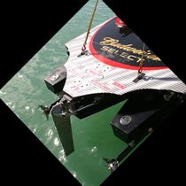
LATHAM RUDDER SYSTEMS are the ultra-high performance rudders in the industry today and some of the fastest boats in offshore racing are using Latham Marine’s racing rudder. All the components including the rudder blade, the transom support bracket and even the attaching studs are all designed to withstand extreme shock loads that are prevalent in offshore racing. Another unique feature is the Latham exclusive ‘quick change’ design which allows the rudder to be changed without the need to remove and re-align the two outer pintle plates that sandwich the blade associated with most rudder designs. The kit includes the rudder blade, transom support bracket, steering cylinders and mounts and attaching studs.
Send Us A Message
- 280 S.W. 32 Court Fort Lauderdale, FL 33315
- Tel. 954-462-3055
- 800-422-7267
- [email protected]

Only made in the USA
- Types of Sailboats
- Parts of a Sailboat
- Cruising Boats
- Small Sailboats
- Design Basics
- Sailboats under 30'
- Sailboats 30'-35
- Sailboats 35'-40'
- Sailboats 40'-45'
- Sailboats 45'-50'
- Sailboats 50'-55'
- Sailboats over 55'
- Masts & Spars
- Knots, Bends & Hitches
- The 12v Energy Equation
- Electronics & Instrumentation
- Build Your Own Boat
- Buying a Used Boat
- Choosing Accessories
- Living on a Boat
- Cruising Offshore
- Sailing in the Caribbean
- Anchoring Skills
- Sailing Authors & Their Writings
- Mary's Journal
- Nautical Terms
- Cruising Sailboats for Sale
- List your Boat for Sale Here!
- Used Sailing Equipment for Sale
- Sell Your Unwanted Gear
- Sailing eBooks: Download them here!
- Your Sailboats
- Your Sailing Stories
- Your Fishing Stories
- Advertising
- What's New?
- Chartering a Sailboat
- Sailboat Rudder
Making a Sailboat Rudder for s/y Alacazam
It's not enough just for a sailboat rudder to steer the boat effectively, it should also contribute to the keel's job of providing lift to windward, and for it to do this it must be designed as a hydrodynamic foil.
Of course a rudder doesn't have to provide lift, but it's a wasted opportunity if it doesn't.
As with an aircraft's wing, to develop lift the sailboat rudder must have water flowing over its leading edge at an angle of attack.
Fortunately for us sailors, the pressure of air on the windward side of the sails, pushes the boat bodily off course slightly and it's this leeway that provide the angle of attack - or angle of incidence- that enables our keels and rudders to provide lift.
But What Type of Sailboat Rudder would be Best for Alacazam ?
First, we considered twin transom-mounted rudders. The usual argument for twin rudders is:
- as the boat heels, the leeward rudder is more deeply immersed and provides better control, and
- the boat, resting on the keel and two rudders can dry-out upright.

But in the end we decided against the twin rudder arrangement because:~
- with Alacazam's deep draught (7 feet, or 2.2m) the twin rudders wouldn't be deep enough to achieve the drying-out upright benefit, and
- the mechanical complexity of tiller steered twin rudder system went against one of our key design principles - keep it simple, and
- with no propwash flowing over the rudders, manoeuvring under power in tight situations would be a little too interesting for my tastes.
So the conventional single rudder approach it was to be. But what type of sailboat rudder?
A Transom-Hung Rudder
We liked the simplicity of this arrangement, but it didn't suit Alacazam's hull design at the stern. We wanted a sugar-scoop design with a bathing platform to allow easy access from the dinghy which ruled out a transom hung rudder. Similarly, it meant that mounting the servo-pendulum self-steering gear would be unnecessarily complicated.
Spade Rudder

The spade rudder is the most efficient of all sailboat rudders, which is why you're unlikely to see any other design on racing yachts.
The absence of a skeg means that all of its area is used to apply a turning force to the hull, minimizing wetted area and associated drag.
The area ahead of the stock helps to balance the rudder, making life easier for the helmsman.
But it's not the most robust design, being entirely dependent on the strength of rudder stock to resist impact damage.
Theoretically it's just a matter of engineering, but high performance spade rudders just aren't thick enough to incorporate a rudder stock of sufficient diameter for ultimate security.
Skeg-Hung Rudder

Other than those rudders hung on the following edge of long keels, the skeg hung rudder - supported top and bottom on a full length skeg - is the most robust design.
Without a portion forward of the stock, there's no balancing force to take the load of the helmsman's arms - so loads can be quite heavy in some designs.
Nevertheless, it's a very popular design for offshore cruising boats.
Semi-Balanced Rudder

This design of sailboat rudder is something of a compromise between the spade rudder and the full skeg rudder.
Supported at its mid-point by a half-depth skeg, it benefits by the area forward of the stock, below the skeg.
This applies a balancing force as the rudder is turned making the steering lighter than it would otherwise be. And it was this design we chose for Alacazam's rudder.
Making Alacazam's Rudder

A typical productions boat's rudder is likely to have been fabricated as shown here, with two GRP mouldings 'clamshelled' around a foam core.
Not the most reliable arrangement you might think - and you'd be right.
We wanted something a little more robust for Alacazam's rudder.

But first, the rudder stock.
We fabricated this from a 2" (50mm) diameter stainless steel solid bar and welded on flat stainless tangs that would be embedded within the rudder.
The Admiralty Bronze casting will eventually connect the rudder to the skeg.

With the rudder stock fabricated, we began the construction of the rudder core.
It was made up from half inch (12mm) marine ply sheets, cut to shape and incorporating cut-outs for the tangs, screwed and glued together.
The rudder and skeg was built up as a single unit at this stage.
The rudder design software generated coordinates for various stations along the rudder, and we used these to cut templates so that we could get the shape right.
Shaping the rudder profile was done by hand, initially with a plane to remove the excess, then with a file and diminishingly coarse grades of sandpaper.
Once the rudder profile matched the appropriate template we removed the section that would form the skeg.
Next, the rudder was fitted to the stock with any gaps between the tangs and the ply taken up with high-strength epoxy 'gloop'.
Finally both the rudder and the skeg were sheathed in several layers of epoxy-glass rovings before being filled and faired with epoxy fairing compound.
Fitting the Sailboat Rudder

The skeg was letter-boxed through a slot cut in the hull, securely braced internally and bonded to it with fillets of high-strength epoxy and epoxy glass rovings.
Inside the hull we had constructed a GRP tube to contain the stock, and the skeg was also bonded to the lower end of that.
The rudder was then securely fitted to the stock via the bronze bearing, and located at the top of the rudder by a stainless steel bearing.
That's it, we now have a very robust and efficient rudder securely attached to Alacazam's hull.
Recent Articles
The CSY 44 Mid-Cockpit Sailboat
Sep 15, 24 08:18 AM
Hallberg-Rassy 41 Specs & Key Performance Indicators
Sep 14, 24 03:41 AM
Amel Kirk 36 Sailboat Specs & Key Performance Indicators
Sep 07, 24 03:38 PM
Here's where to:
- Find Used Sailboats for Sale...
- Find Used Sailing Gear for Sale...
- List your Sailboat for Sale...
- List your Used Sailing Gear...
Building Alacazam...

But why go to the bother of building your own boat?

Copyright © 2024 Dick McClary Sailboat-Cruising.com
PRESS RELEASES
< Back to all news
RACE RESULTS
FARR MAGAZINE
GET UPDATES
ENVIRONMENT
DESIGNS BY LENGTH
DESIGNS BY NUMBER
VOLVO OCEAN RACE
SUPERYACHTS
AMERICA'S CUP
Rudder Re-Design
Published May 16, 2017
It is nearly impossible and very cost prohibitive to improve the performance of a yacht by changing the existing hull shape. However it is relatively easy and inexpensive to alter the keel, rudder, rig and sails to improve performance. Therefore, as part of our regular consulting services, it is common for our clients to approach us seeking improvements to their appendages.
One of the exceptional aspects of our legacy in the field of yacht design is the performance of our production cruiser/racer designs under various handicapping systems in races around the globe. Yachts like the Beneteau First 40.7, First 36.7, First 10R, First 40, First 35 and Farr 395 have long track records of achievement in sailing’s most prestigious races. However, because these yachts are very much production-oriented, the original appendage designs were compromised due to restrictions in the use of higher tech materials and the need to constrain build costs. Therefore, replacing the factory supplied rudder on these types of production cruiser/racers with a more racing-oriented rudder yields excellent bang-for-the-buck to improve the performance and handling of a production cruiser racer.
With this in mind, Farr Yacht Design has created new and improved rudder designs for the Farr 395, Beneteau First 10R and Beneteau First 40.7. These new designs feature carbon fiber rudder posts, higher aspect ratio rudder blades, and the latest in foil technology. These modifications result in reduced weight and lower drag while, at the same time, increasing the stiffness, strength and safety factor. We view the rudder as a critical safety feature of any yacht, so each new rudder is designed to exceed the minimum scantling requirements required by the ISO 12215 Rule.
Our typical design process starts with a review of the handling capabilities of the existing rudder. We consult with owners and experts who have sailed extensively on these yachts to get their feedback on how the existing rudder performs in a variety of conditions. With that information at hand, and using our advanced VPP tools we make adjustments to the blade area, span, chord length and foil section shape to address any perceived weaknesses and make other improvements. We also review the balance of the rudder blade making sure that the new design gives optimum feel and rim load.
We have collaborated with Competition Composites, Inc. (CCI) to build these replacement rudders. Owners of these yachts now have access to a vastly improved rudder design at an affordable price. All of these rudders are plug-and-play. They can be fitted into existing bearings and attached to the existing steering systems with little or no modifications required. The rudders were designed using our advanced parametric 3D modeling tools and tailored to suit the production methods of CCI.
Contact FYD to hear how our advanced appendage design capabilities can improve the performance of your cruiser/racer.
Farr Yacht Design
100 Severn Avenue, Suite 101
Annapolis, MD 21403
© 2018
- New Sailboats
- Sailboats 21-30ft
- Sailboats 31-35ft
- Sailboats 36-40ft
- Sailboats Over 40ft
- Sailboats Under 21feet
- used_sailboats
- Apps and Computer Programs
- Communications
- Fishfinders
- Handheld Electronics
- Plotters MFDS Rradar
- Wind, Speed & Depth Instruments
- Anchoring Mooring
- Running Rigging
- Sails Canvas
- Standing Rigging
- Diesel Engines
- Off Grid Energy
- Cleaning Waxing
- DIY Projects
- Repair, Tools & Materials
- Spare Parts
- Tools & Gadgets
- Cabin Comfort
- Ventilation
- Footwear Apparel
- Foul Weather Gear
- Mailport & PS Advisor
- Inside Practical Sailor Blog
- Activate My Web Access
- Reset Password
- Customer Service

- Free Newsletter
Blue Jacket 40 Used Boat Review

Catalina 270 vs. The Beneteau First 265 Used Boat Match-Up

Ericson 41 Used Boat Review

Mason 33 Used Boat Review

How to Create a Bullet-Proof VHF/SSB Backup

Tips From A First “Sail” on the ICW

Tillerpilot Tips and Safety Cautions

Best Crimpers and Strippers for Fixing Marine Electrical Connectors

Polyester vs. Nylon Rode

Getting the Most Out of Older Sails

How (Not) to Tie Your Boat to a Dock

Stopping Mainsheet Twist
Fuel Lift Pump: Easy DIY Diesel Fuel System Diagnostic and Repair

Ensuring Safe Shorepower

Sinking? Check Your Stuffing Box

What Do You Do With Old Fiberglass Boats?

Boat Repairs for the Technically Illiterate

Boat Maintenance for the Technically Illiterate

Whats the Best Way to Restore Clear Plastic Windows?

Stopping Holding-tank Odors

Giving Bugs the Big Goodbye

Galley Gadgets for the Cruising Sailor

The Rain Catcher’s Guide

Sailing Gear for Kids

What’s the Best Sunscreen?

UV Clothing: Is It Worth the Hype?

Preparing Yourself for Solo Sailing

R. Tucker Thompson Tall Ship Youth Voyage

On Watch: This 60-Year-Old Hinckley Pilot 35 is Also a Working…

On Watch: America’s Cup

On Watch: All Eyes on Europe Sail Racing

Dear Readers
- Systems & Propulsion
Rudder Mods for Low-speed Docking

A ny sailor who has tried to wrestle a full-keel ketch with a barn-door rudder into a tight slip has probably wondered if they could modify the rudder to improve low-speed maneuvering without slowing the boat down under sail. As it turns out, there are several rudder design tweaks designed to improve control on ships, large working boats, and trawlers, but few have been implemented widely in the sailing world.
Most sailors have a general understanding of how a rudder works, because the concepts of lift and drag that apply to sail trim and keels also apply to what happens underwater with respect to rudder trim. The rudder’s angle in relation to the flow of water as the boat moves through the water is its angle of attack. When this angle changes, it creates a low-pressure zone on one side of the rudder that “lifts” the rudder forward toward that zone. On the other side of the rudder is drag, the enemy of lift.
At low speed, or when making sharp turns—two essential features of any docking exercise—the lift is so anemic that drag can cause the rudder to stall, and the skipper must rely on other forces such as prop walk (forces generated by the propeller’s rotation) or prop wash to squeeze the boat into its slip. For responsive steering when docking, you want a rudder profile that has a healthy lift-to-drag ratio at low speed. This is not possible using the most popular rudder designs, which are based on foils developed by the National Advisory Committee for Aeronautics (NACA). The NACA foil shapes, designed to provide optimal lift-drag ratios for aircraft operating at higher speeds when flying a relatively straight line, are not the best suited to making sharp turns at slow speeds (see illustration, page 20).
Our dive into the world of rudder designs for low-speed maneuvering was triggered by questions from a reader who was frustrated with the close quarter maneuvering capabilities of his full-keel sailboat. He was happy with the boat’s performance when sailing, but under power, and particularly at low speed, the boat simply would not turn. He had read that if he attached a 90-degree angle iron on each side of his rudder’s trailing edge, his rudder would be far more effective.
Since a modification that adds drag at the trailing edge seems to go against the conventional wisdom that a knife-like trailing edge is best for sailboats (see “Building a Faster Rudder,” PS June 2021), he was baffled to say the least. We were curious, too. Are there unconventional rudder profiles—at least in the world of sailing—that might be a better fit for a boat like his? When docking in close quarters, an auxiliary-powered sailboat effectively behaves as a powerboat, so it is worth looking at what rudder modifications have helped trawlers, fishing boats, or commercial ships tighten their turning radius.
SAILBOAT RUDDERS
Sailboat rudders serve as both a control device for steering and lateral plane to develop lift. When sailing straight, or nearly so, the rudder operates at a relatively steady, low angle of attack. The low angle is nowhere near one that would interrupt the flow of water and cause the rudder to stall.
On a well-designed sailboat in good trim, weather helm is about 2-5 degrees. This is the rudder angle required to steer a straight course while reaching. But that’s just part of the equation. Like the keel, the rudder is impacted by leeway, slipping about 5- to-10 degrees in relation to the course steered. This means the rudder’s actual angle of attack through the water is about 7-to-15 degrees.
An efficient NACA rudder profile will provide a favorable lift-to-drag ratio up to an angle of attack of about 16-to-20 degrees, so you have limited “wiggle-room” before the rudder will begin to stall.
Because a sailboat rudder needs to provide lift at relatively low speeds, it needs a relatively large surface area and a foil shape with a high aspect ratio. Aspect ratio is the ratio between the chord—the straight-line distance between the leading and trailing edges of the foil—and the foil’s span, or length (depth in the case of a sailboat rudder).
These narrow and deep NACA-based rudder shapes are designed for maximum efficiency going to windward. They provide adequate maneuverability under sail but aren’t very efficient under power. Racing designs exacerbate low-speed steering problems by putting the rudder as far from the prop as possible to minimize turbulence at the rudder. This makes it virtually impossible to nudge the stern to port or starboard by redirecting propwash with a sharply turned rudder a common tactic during docking maneuvers.

POWERBOAT RUDDERS
The rudder on an inboard-powered trawler or cabin-cruiser by comparison, operates in the high velocity slipstream of the propeller. It is not asked to resist the steady sideways pressure of the wind, only to provide turning force. Any additional rudder area hanging below the prop’s stream only adds drag (and draft) with very little benefit. The profile must be low drag, and as a result, many powerboat rudders are nothing more than a flat plate welded to a shaft with whatever reinforcement is required. This provides acceptable docking performance so long as the timely bursts of power are applied at the right rudder angle. Larger ships, with a lower power-to-mass ratio, require some additional help.
SHIP RUDDERS
Ocean going ships focus on straight-line efficiency. They are assisted by a harbor tug when docking. They use rudder sections like those of sailboats for slightly improved lift-to-drag ratios, but the rudder remains small. However, some ships, including tugs, coastal freighters, and barges, require greater maneuverability. When navigating in constrained waterways, these ships and work boats spend a great deal of time with the helm turned at high angles.
As a result, naval architects have developed different rudder sections that will operate effectively at much higher angles than traditional NACA sections we see on sailboat rudders. These convex shapes are referred to as “fishtail sections”. Examples of fishtail rudder designs are the Schilling and Thistle rudders (proprietary foil sections named by their designers), which can reduce the turning circle of a boat by as much as 50 percent. Some examples of these low-speed designs are shown alongside conventional sailboat rudder (NACA) profiles in the illustration.
If you have a spade rudder located a few feet away from the prop, you won’t gain anything with a fishtail section. Effective use of prop-wash—along with an experienced hand at the helm—should be enough to get you in and out of a slip. However, if you are the owner of a shoal draft boat with a short rudder, a full-keel cruising boat, or a motorsailer, and have been kept awake by visions of bow thrusters dancing in your head, read on.

LOW SPEED STEERING UNDER SAIL
At low angles of attack, water flows relatively evenly around both sides of the rudder, creating minimum drag. This streamline, also called laminar flow, remains “attached” to the rudder’s surface. Any change in relative speed or direction that interrupts this flow can cause the rudder to stall.
When a rudder stalls, the water on the low-pressure side is no longer deflected effectively, creating a separation bubble that reduces lift on the low-pressure side. At the same time, drag on the high-pressure side of the rudder continues to rise. As result, the low-pressure side of the rudder’s trailing edge becomes less important, because it is within the eddy zone (separation bubble, see adjacent illustration). Since there is very little water flow over this surface, it does not create much drag. Only the flap on the high-pressure side sees flow and generates drag. We’ll come back to the latter point, but it should be apparent that sailboat rudders cannot operate in the stalled region; the drag is too high for windward work, and the lift is too low for high-speed corrections in big waves.
When maneuvering under power at low speed we need more lift, so drag doesn’t really matter. To overcome any drag, we can just use more throttle. Airliners use massive flaps when landing. The drag is horrendous, but since they are descending and trying to reduce speed, they have plenty of reserve power to overcome drag. The tradeoff is worth it. During take-off, when they have less power to spare, they use zero flaps (and sometimes high-lift devices called slats on the wings’ leading edge).

In search of new symmetrical shapes with the same high lift characteristics as an asymmetrical airplane wing, ship designers began experimenting. In fact, some ships use rudders with flapped trailing edges, like airplane flaps, but simpler. After much trial and error, simpler, non-articulating sections, referred to as fishtails, were found to have many of the same beneficial characteristics as a jet wing.
As a result of this research, a series of foils were developed in Germany by the Hamburgische Schiffbau Versuchsanstal (Hamburg Model Ship Basin) and the Institute für Schiffbau (Institute for Ship Building). Named after their place of origin, these shapes were designated HSVA shapes and HVS shapes. A variety of proprietary wedges and fishtails grew from there.
When a vessel is steering a straight path and the rudder has a low angle of attack, HSVA and HVS shapes create slightly more drag than NACA profiles of equal lift. However, they delay stall and create more lift at higher angles. Although the wedge or flap slightly increases drag, once the foil stalls, this drag is minimized because it is in the separation bubble.
As shown in the example foils (see Figure 1), the “fishtail” is a wedge-like section at the trailing edge. Generally, the maximum thickness of wedge will be no more than the maximum thickness of the rudder. The ideal thickness of a sailboat rudder is about 20 percent of the chord—the distance between the leading and trailing edge measured parallel to the normal laminar flow (see Figure 2). Ideally, a fishtail rudder will be based on a concave HSVA or HVS section, but simply adding a wedge at the trailing edge of NACA profile or a flat plate has proven to be a cost-effective way to achieve similar performance.

ADDING END PLATES
Another feature of high-lift rudders are endplates. Just as the name implies, these are plates at the top and bottom “ends” of the rudder. Their purpose is to help direct laminar flow over the rudder, by reducing loss of flow at the rudder tips (known as tip loss).
You don’t often see endplates on sailboat rudders or keels because they can create a lot of turbulence and drag. In addition, the deep, narrow (high-aspect) rudder of a sailboat will suffer much less tip loss than a broad shallow (low-aspect) one found on most powerboats. Finally, the narrow gap between the top of the rudder and the flat stern section of a racing sailboat effectively creates an endplate at the top of the rudder, eliminating the need for one there.
Endplates will be more appealing to owners of motorsailers, heavy-displacement sailboats with barn door rudders, or other large auxiliary sailboat designs that can create headaches during docking. On these boats, the additional drag under sail may be worth better maneuverability under power.
These “endplates” on a sailboat rudder don’t have to be at the ends of the rudder as they are on a powerboat; they can be at the top and bottom of the rudder’s prop wash zone to help direct laminar flow and improve rudder lift under power. On a motorsailer, to make full use of the prop thrust, the distance between the end plates should about 120 percent of the prop diameter. The plate width should be about 120 percent of the maximum thickness of the foil, or, in the case of a thin, flat rudder, 20 percent of the chord.

OTHER CONSIDERATIONS
Adding endplates or a fishtail can have some unintended consequences. For example, it will move the rudder’s center of effort aft, making it harder to steer. The change is most pronounced at low speeds with the helm well over, but forces are low, so this is not typically a problem. At higher speeds, the difference will be more noticeable, and this is something to look for during a sea-trial before you commit to a permanent change.
To get the maximum benefit of a fishtail rudder with or without endplates, one could also experiment with moving the end stops, which limit the maximum angle you can turn the rudder to either side—although we’d be very careful with this. Rudder end stops generally limit rudder angle to 35 degrees, the maximum angle at which conventional rudder designs are effective.
A fishtail design will work beyond this limit, up to 45 degrees, potentially reducing turning radius by up to 50 percent at speeds of 2-to-4 knots. However, increasing rudder angle will also increase loads on the rudder stock and rudder bearing when the boat is in reverse or, more seriously, getting tossed backward by a wave in extreme conditions. Although we have few qualms about experimenting with end plates and wedges, we wouldn’t mess with rudder stops on an offshore cruising boat without some professional guidance from an engineer or naval architect.

While this seems like a lot of effort to make docking easier, having control at low speed can be beneficial at sea, as well. You will have better control when powering in adverse weather, slowing down to the minimum speed that allows for control—steerage speed—which can help in heavy weather.
This report is not advocating for rudder redesign on a sailboat that steers adequately at low speeds under power. Nor should it be construed as surefire way to fix steering problems on problem boats, although we’re optimistic that it will help. Based on solid evidence from the world of trawlers, working boats and ships, it is a concept that deserves more study. We have not yet been able to test fishtail rudders on our own sailboats, but many vessels, both commercial and recreational—have added fishtails with positive results. We’d be interested in hearing from sailors who might have experimented with either.
As for endplates, we strongly believe that they are smart idea on trawler rudders; the only downside is that it can snag weed. To prevent this, we would leave the forward portion of the plate flush with the leading edge of the rudder and then rake it in a streamlined form as it extends aft. Shallow-draft motorsailers with trawler-like rudders could also benefit from streamlined endplates. As mentioned, the endplates don’t have to be at the rudder tips, they could be positioned to maximize prop wash.
Adding a fishtail becomes more complicated. What angle works best? How will it impact rudder balance? The HVSA sections are a good starting point when conceptualizing fishtail sections. Although adding a simple 90-degree angle at the trailing edge is common, naval architect Dave Gerr, the author of several books on yacht design and engineering, suggests starting with a metal plate that can be adjusted to alter its angle.
If you want to experiment, you could attach a stainless-steel sheet metal strips to each side of the rudder. The metal would be bent at an angle that mimics the shape of your preferred fishtail. During sea trials, you can adjust the angle until you find one that works. If you are using stainless-steel bolts or screws to fasten the sheet metal, you will want to be extremely careful about not allowing any water into the rudder laminate or foam core. Seal the core with epoxy as you would when fastening deck hardware or fasten the angle using high-strength adhesive.
If the angle doesn’t seem to help, you can take it off, fill the holes, and master the art of using spring lines to squeeze your boat in and out of its slip on windy days. If your improvised fishtail does improve low-speed steering, consider shaping a more permanent section that can be bonded to the original rudder—or building a new rudder to the improved design. If you are also adding endplates, the fishtail sections do not need to be mechanically attached to the endplates, but they should be very close.
Full keel sailboats are never going to turn on a dime; they like to go straight. But there is plenty of evidence that a fishtail section, such as the concave IFS61, located just aft of the prop, could improve low-speed performance. We doubt this fishtail section located directly behind a 3-to-4 blade fixed prop will have any negative effect on sailing—the flow is turbulent behind the prop anyway. As for the potential benefits, based on what we’ve seen in the powerboat world, a low-speed rudder design is worth investigating.
REFERENCES:
SHIPS AND OFFSHORE STRUCTURES Volume 12 (2017), Issue 4. “Sixty Years of Research on Ship Rudders: Effects of Design Choices on Rudder Performance,” by Jialun Lee and Robert Hekkenberg. www.tandfonline.com
GREAT HARBOUR TRAWLERS – www.greatharbourtrawlers.com
MARINE TECHNICAL SOCIETY 2012 CONFERENCE. “Station Keeping with High Performance Rudders, ” by Joerg Mehldau www. dynamic-positioning.com .
OCEAN NAVIGATOR June/July 2005. “High Lift Rudders and Improved Boat Handling, ” by Dave Gerr. www. oceannavigator.com
PROFESSIONAL BOATBUILDER. “Keel and Rudder Design, ” by Eric Sponberg. www.ericwsponberg.com
T he rudder plays a much simpler role on a power boat. It doesn’t have to resist leeway to the same degree that a sailboat does, nor does it have to help provide the significant lift required to make windward progress. However, sailboats maneuvering under power alone behave similarly to trawlers. The increasing popularity of fish tale rudders among trawlers prompted our research into their potential for cruising sailboats that might benefit from the design.

1. This Defever trawler rudder has end plates for better steering at low speeds. There is also a slight “fishtail” flare at the trailing edge.

2. The flare consists of a triangular strip of 3⁄8 inch steel welded to each side. The endplates are flat stock welded to the end of the rudder.

3. Directly aft of a big four-blade prop, this fishtail wedge helps the boat achieve a tighter turning radius by improving lift at extreme rudder angles.

4. The wedge on this high-lift rudder on this 50-foot trawler is much more pronounced than the one on the Defever (images 1 and 2).
RELATED ARTICLES MORE FROM AUTHOR
My boat is a Swallow Craft Swift 33. It had a “barn door” skeg hung rudder. it was a bear to steer and zero directional control in reverse. I’ve forgotten most of the math but basically I lengthened the rudder 11″ and extended the rudder forward of the pivot point. There was a fair amount of math involved (for me anyway). Now I had a hydrodynamic counterbalance forward was like power steering and some control in reverse. Great article, just adding my experience.
LEAVE A REPLY Cancel reply
Log in to leave a comment
Latest Videos

Cabo Rico 34 Boat Review

Super Shallow Draft Sailboat: The Leeboard Sharpie

Hans Christian 41T – Boat Review

Seven dead after superyacht sinks off Sicily. Was the crew at...
Latest sailboat review.

- Privacy Policy
- Do Not Sell My Personal Information
- Online Account Activation
- Privacy Manager
- Switch skin
Understanding Spade Rudders: Benefits, Materials, and Design Considerations

A spade rudder is a modern innovation in marine engineering, predominantly utilized in contemporary sailing vessels and motor yachts. This rudder type is distinct from traditional designs due to its free-standing nature, connected solely to the hull via the rudder stock. This unique configuration endows spade rudders with enhanced manoeuvrability and responsiveness, key attributes prized by modern sailors.
The structure of a spade rudder is relatively straightforward yet highly effective. It consists of a rudder blade , which is the primary surface that interacts with water to steer the vessel, and a rudder stock, a robust shaft that connects the blade to the vessel’s hull. Unlike conventional rudders that are affixed to the keel or skeg, spade rudders are independent, allowing for greater freedom of movement. This design minimizes drag and improves the hydrodynamic efficiency, contributing to better overall performance.
Historically, the development of the spade rudder marks a significant advancement in naval architecture. Traditional rudders, often cumbersome and less responsive, were gradually replaced as spade rudders demonstrated superior handling characteristics. The adoption of spade rudders began in earnest in the mid-20th century, coinciding with advancements in materials science and hydrodynamic research. These rudders quickly became the preferred choice for performance-oriented vessels, where agility and precision are paramount.
Spade rudders are commonly found on a wide range of vessels, from high-performance racing yachts to luxurious motor yachts. Their versatility and effectiveness make them suitable for various applications, including leisure cruising, competitive sailing, and long-distance voyaging. The ability to execute sharp turns and maintain course stability under varying conditions underscores their popularity among sailors seeking both efficiency and control.
In essence, the spade rudder’s design and functionality represent a blend of simplicity and sophistication, offering a pivotal advantage in modern nautical endeavors. As technology and materials continue to evolve, the spade rudder remains a cornerstone of innovative marine design, ensuring vessels navigate with precision and confidence.
Components of Spade Rudder
A spade rudder is a free-standing rudder that is not supported by a keel or skeg, making it a critical component for steering in many vessels. Here are the main components of a spade rudder:
1. Rudder Blade
- Shape : The rudder blade is the primary surface that interacts with water to steer the vessel. It’s typically designed with a hydrodynamic foil shape to provide lift and minimize drag.
- Core : The interior of the rudder blade often has a lightweight core, such as foam or balsa wood, which provides shape and structure.
- Skin : The exterior of the rudder blade is typically made of strong materials like fiberglass, carbon fiber, or metal to withstand the forces exerted during operation.
2. Rudder Stock (Shaft)
- Material : The rudder stock is usually made of strong, corrosion-resistant materials such as stainless steel or aluminum.
- Function : It connects the rudder blade to the steering system inside the boat and transmits the steering forces.
3. Rudder Bearings
- Upper Bearing : Supports the top of the rudder stock, allowing it to rotate smoothly. It’s located where the stock passes through the hull.
- Lower Bearing : Provides additional support at the lower end of the rudder stock, reducing stress on the upper bearing and ensuring smoother operation.
- Materials : Bearings are usually made of materials like bronze, Delrin, or other engineered plastics that resist wear and corrosion.
4. Rudder Tube/Housing Wall Thickness
- Function : The rudder tube encloses the rudder stock and passes through the hull of the vessel, providing a sealed path to prevent water ingress.
- Material : It is usually made from fiberglass, composite materials, or metal.
5. Tiller or Steering Arm
- Tiller : A lever attached to the top of the rudder stock for manual steering. Common in smaller boats.
- Steering Arm : In larger boats with wheel steering, a steering arm connects to the rudder stock and is linked to the steering mechanism (like cables or hydraulics).
6. Quadrant or Lever
- Function : Converts the rotational motion of the steering wheel into lateral motion, which moves the rudder. It’s often connected to the rudder stock via the steering cables or hydraulic system.
- Material : Typically made of metal, often stainless steel or aluminum.
7. Gudgeons and Pintles (if applicable)
- Function : These are pivot points that support the rudder on some designs. However, in true spade rudders, these are generally not used since the rudder is unsupported except at the stock.
8. Sacrificial Anode
- Purpose : A zinc or aluminum anode is often attached to the rudder to prevent corrosion through galvanic action, particularly in saltwater environments.
9. Jumping Collar
Prevents Vertical Movement : The primary function of the jumping collar is to prevent the rudder stock from moving upwards. This is especially important in spade rudders, where the entire rudder is supported by the bearings and the rudder stock. It also Locks the Rudder in Position : It holds the rudder stock in a fixed vertical position, ensuring consistent and reliable steering.
These components work together to provide effective steering control, balancing the need for strength, durability, and hydrodynamic efficiency.
How to Design a Spade Rudder
Designing a spade rudder is a multifaceted process that requires meticulous attention to various factors such as the vessel’s size, intended use, and operating environment. The rudder’s shape and size play a critical role in determining its effectiveness. The rudder blade should be proportionate to the boat’s dimensions and capable of generating adequate lift and minimal drag. A well-designed spade rudder ensures enhanced maneuverability and stability, contributing to the overall performance of the vessel.
The type of rudder stock is another crucial element in the design. Typically made from high-strength materials like stainless steel or composites, the rudder stock must withstand substantial loads without compromising integrity. The selection of the rudder stock material should be based on factors like corrosion resistance, strength-to-weight ratio, and ease of maintenance. The method of attachment to the hull is equally important; it must ensure robust connectivity while allowing for smooth operation and minimal wear over time.
Modern design tools such as Computational Fluid Dynamics (CFD) have revolutionized the way spade rudders are designed. CFD simulations allow designers to model fluid flow around the rudder, enabling the optimization of its shape and performance. These simulations can help identify potential issues such as turbulence and cavitation, which can be mitigated through iterative design adjustments. The use of CFD and other advanced modeling tools can significantly enhance the efficiency and reliability of spade rudders.
Best practices in spade rudder design include conducting thorough load analyses and fatigue assessments to ensure long-term durability. It’s also advisable to incorporate feedback from real-world use cases and previous designs to refine and improve the rudder. Keeping abreast of the latest advancements in materials science and fluid dynamics can provide valuable insights and help in developing cutting-edge spade rudders.
Designing a spade rudder involves several key steps, focusing on hydrodynamics, structural integrity, and overall performance.
1. Understand the Requirements
- Vessel Type : The size and type of the vessel (sailboat, motor yacht, etc.) will dictate the rudder size and shape.
- Performance Needs : Consider whether you need more maneuverability, stability, or a balance between the two.
- Materials : Choose between materials like fiberglass, carbon fiber, or metals, depending on weight, strength, and cost requirements.
2. Hydrodynamic Design
- Rudder Shape : A spade rudder is typically a balanced or semi-balanced design with a foil shape for efficiency. Use an airfoil shape like NACA profiles for optimal lift and drag characteristics.
- Aspect Ratio : A higher aspect ratio (long and narrow) reduces drag and improves efficiency but can be structurally challenging.
- Chord Length and Thickness : Determine the chord length (front to back of the rudder) and thickness, aiming for a balance between structural integrity and hydrodynamic performance.
3. Structural Design
- Stock (Shaft) : The rudder stock should be strong enough to withstand loads without bending. Common materials include stainless steel or aluminum. Calculate the required diameter based on the loads expected.
- Attachment to Hull : The rudder stock needs to be securely attached to the hull, typically through bearings and a support structure inside the hull.
4. Load Calculations
- Hydrodynamic Forces : Calculate the forces acting on the rudder at various speeds and angles to ensure the design can handle maximum loads.
- Torque and Bending Moments : Ensure the stock and rudder structure can withstand the torque and bending moments produced under load.
Here is guidelines from IACS S10. It indicates shear force and bending moment diagram based on rudder shape and stock dimension.

Materials Used in Spade Rudder Construction
The efficacy and longevity of a spade rudder are greatly influenced by the materials employed in its construction. Among the commonly utilized materials are aluminum, stainless steel, and various composites such as carbon fiber. Each of these materials presents unique characteristics that make them suitable for different applications, balancing factors such as strength, weight, corrosion resistance, and cost.
Aluminum stands out for its lightweight nature and excellent corrosion resistance, making it a popular choice for recreational and smaller commercial vessels. Its relatively low cost also contributes to its widespread use. However, aluminum’s strength is lower compared to other materials, which can be a limitation in demanding marine environments or for larger vessels requiring robust structural integrity.
Stainless steel or Carbon steel offers superior strength and durability, making it well-suited for larger commercial vessels and those operating in harsh marine conditions. Its high resistance to corrosion ensures longevity, even when exposed to saltwater environments. Nonetheless, stainless steel is significantly heavier and more expensive than aluminum, which can be a drawback for weight-sensitive applications.
Composites, particularly carbon fiber, are increasingly favored in the construction of spade rudders due to their exceptional strength-to-weight ratio. Carbon fiber composites are incredibly strong yet lightweight, which can enhance the performance and efficiency of the vessel. Additionally, these materials exhibit excellent fatigue resistance and are highly resistant to corrosion. The main downside is the high cost associated with carbon fiber, which can be prohibitive for some projects. Additionally, the manufacturing process for composites can be complex, requiring specialized knowledge and equipment.
Benefits of Using a Spade Rudder
Spade rudders have revolutionized maritime navigation, offering substantial advantages over traditional rudder designs. One of the most significant benefits is their free-standing design, which minimizes drag. This reduction in drag not only enhances a vessel’s speed but also contributes to improved fuel efficiency. Empirical data suggests that vessels equipped with spade rudders can experience up to a 10% increase in fuel efficiency, a crucial factor for both commercial and recreational vessels aiming to reduce operational costs.
Another primary advantage of spade rudders is their superior maneuverability. The design allows for more precise control, making it easier to navigate tight spaces or perform complex maneuvers. This is particularly beneficial for vessels operating in congested harbors or undertaking intricate docking procedures. Expert opinions in the field underscore that spade rudders provide a more responsive and agile handling experience, which can be a decisive factor in critical situations.
Additionally, spade rudders are often lighter than their traditional counterparts. The reduction in weight contributes to better overall performance and buoyancy. This weight advantage is due to the absence of a supporting structure, which is common in older rudder designs. The lighter weight not only improves speed but also reduces the strain on the vessel’s steering mechanism, enhancing the longevity of the steering system.

NV Tech Desk
Germany approves meyer werft bailout, sunken mv itt puma ship’s cargo-laden containers wash ashore odisha’s beach, navantia australia’s design capabilities drive hobart class destroyer upgrade forward, ghost shark xl-auv arrives in the united states, in memory of claus winter graugaard, mitsui o.s.k. lines expands stake in modec, solidifying strategic partnership, more than 180 participants celebrate opening of nyk’s hokkaido branch, dp world cochin achieves record-setting performance with 73,636 teus handled in july 2024, india aims to be global leader in green hydrogen, ammonia, jiangnan shipbuilding bags new order for 93,000 cbm ammonia carriers, subscribe to our mailing list to get the new updates.
Lorem ipsum dolor sit amet, consectetur.
- Competitions
- British Yachting Awards
- Southampton Boat Show
- Print Subscription
- Digital Subscription
- Single Issues
- Advertise with us
Your special offer
Subscribe to Sailing Today with Yachts & Yachting today!
Save 32% on the shop price when to subscribe for a year at just £39.95
Subscribe to Sailing Today with Yachts & Yachting!
Save 32% on the shop price when you subscribe for a year at just £39.95

New Yachts on the Market: Latest Racing & Cruising Designs

In the market for a racing or cruising yacht? It’s been another bumper year for the boatbuilding industry… Sam Jefferson casts his eye over the latest launches.
New yachts: cruising, wauquiez 55.
Wauquiez is a marque that has been much revered in cruising circles since they first started building elegant cruisers back in the 1960s. Their new 55 boat is definitely intriguing and one of the striking features is the centre cockpit with the helm offset to port under a well protected solid plexiglass sprayhood. Another interesting feature is the option of a swing keel which gives you an almighty 4.2m of draft when lowered and 1.6m when raised. Aside from that, the boat dares to be different by supplying two Volvo D2 engines as standard. The interior looks extremely spacious and Lombard has capitalised on full forward sections and plenty of beam to ensure that there is a huge interior space. In addition, the centre cockpit allows for a huge aft owner’s cabin.
wauquiez.com
Moody 48 DS
Moody has been under German ownership as part of the Hanse group for many years now and offers a different sort of cruiser in quality deck saloon cruisers which are designed by Judel/Vrolijk. The new 48 is the first new launch they have made since their 41 2017 and fits between the Moody 45 and 54 in their range. As you’d expect, this is a boat that is big on space and comfort, featuring a big, beamy hull with twin rudders. Performance has not been neglected, however, because she sports a generous rig to push her 21,000kg displacement through the water.
Inspirationmarine.co.uk

Hanse Yachts broke with go to designer of many years Judel/Vrolijk a couple of years back and this was the catalyst behind the launch of a new generation of Hanses designed by the French team of Berret/Racoupeau. In addition to a marked change in styling, with inverted ‘dreadnought bow and hard chines aft giving the boats a more angular look, the main drive seemed to be to up the quality of the boats down below – which was certainly achieved. The new 590 is their biggest boat yet of this new generation and offers easy sailing on a big scale. The new boat features an optional hard top bimini, a tender garage and acres of space down below. The boat will be officially unveiled at Cannes Boat show and promises to be a head turner.

New Cruising Yacht: Maxus 35
Maxus Yachts is a Polish company that made its name. building small trailerable yachts to sail on the Masurian lakes not far from the Russian border. Now the company has moved up a size bracket and their new 35 is bigger and aimed more at offshore sailing than previous designs. The result is a spacious yacht with striking styling and a semi deck saloon arrangement that bathes the saloon with natural light. It all points to promises decent performance and accommodation at a highly competitive price.
northman.pl
French manufacturer Dufour has really pumped up the volume with its latest generation of yachts. The new Umberto Felci designed 44 follows on from the 37 and 41 which have already drawn plaudits thanks to their remarkable ability to create internal volume without looking overly dumpy. The 44 continues in this vein boasting plentiful beam aft and full sections at the bow above the waterline. The interior is positively palatial and there is a choice of three or four cabin layouts.
dufour-yachts.com
Jeanneau Sun Odyssey 350
The Jeanneau Sun Odyssey 350 is the successor to the 349 which was actually launched way back in 2013. At 34’1” excluding the bowsprit she is the starter boat in the range and viewed by the French manufacturer as offering a gateway into sailing for young families.

The boat is designed by Marc Lombard and Piaton Yacht design and, as you’d expect the lines are bang up to date, offering plenty of internal volume via fuller forward sections. Like its predecessor the 349, the new boat is available with a swing keel – a real boon in UK waters. The interior is really quite large and there is the option of twin doubles aft plus a double forward.
jeanneau.com
Elan GT6 Explorer
The Elan GT6 was a very stylish fast cruiser from drawing board of rob Humphreys that has been very well received since its launch. The GT6 Explorer is, as you can imagine a variation on this theme but the manufacturers have identified rthe potential of the boat as a fast blue water cruiser and built on that. As such, the boat fuel and water tankage has been boosted as has battery power. There is also the option of an all electric version utilising Oceanvolt’s pioneering technology.
elan-yachts.com

It has been some years since Danish manufacturers X Yachts realised that if they offered a de tuned Xc cruising range alongside its out and out performance yachts, it would massively enlarge its customer base. The project was a huge success and the Xc range is now into its second generation with the launch of the Xc47. The new launch is one of the first since X Yachts divorce from founder and chief designer Niels Jeppesen and the result is a yacht that leans heavily towards the cruising market, featuring something not far from a deck saloon. The hull lines feature plenty of beam aft and there has obviously been a very conscious effort to up the cruising ante. That said, the boat retains a powerful rig and weight has been kept reasonably modest.
x-yachts.com
New Yachts: Racing
Cf 580 ran 8.
Ran 8 is one of the latest launches from the drawing board of Shaun Carkeek and is a boat that has already cut a dash by taking overall and line honours in the RORC Channel Race. This is a boat that comes from the same mould as Oystercatcher XXXV, launched to much fanfare in 2021. The new boat boasts an uprated water ballast system which is designed to reduce the number of crew required from eight to seven. In addition to this, electric propulsion has been introduced.

The boat is not designed to one particular set of rules and the main aim is simply to design a boat that will go as fast as possible in a range of conditions. The result is a boat optimised for offshore conditions, in which she will be somewhat quicker than a TP52.
carkeekdesignpartners.com
Jeanneau Sun Fast 30
The Sun Fast 30 is a VPLP project who have teamed up with Multiplast to produce a strict one design yacht at what Jeanneau feels is a competitive price. The new boat features full forward sections married to light (2,700kg) displacement, twin rudders and flat aft sections to provide a boat that planes easily and early. The boat is available in two versions: One Design and Club. The one design version features a carbon mast mainsheet track and uprated electronics pack. The Club version has an aluminium mast and a bridle for the mainsheet. The aim is to make it more affordable to club racers.
Clubswan 28: Racing
The Clubswan 28 is a something of a break from tradition for Nautor Swan who have never produced a yacht this small. She rounds off their ClubSwan range and is a pure one design racer set up for four crew. At 1000kg, this Juan Kouyoumdijan design is going to be fast but she appears to be much less technical than boats higher up the range, eschewing foils and keeping things as simple as possible. There is no accommodation.
nautorswan.com

Reichel/Pugh 56 Vasara
The design house of Reichel/Pugh has produced some memorable yachts over the years and the design brief here was for a fast, competitive yacht that was also comfortable and luxuriously appointed down below. There are a number of interesting touches. Most notably, a split backstay and square topped mainsail can be switched out for a single backstay and standard main when cruising. The keel has a substantial 4.1m depth but this can be raised to 2.4m for entering port. The interior is constructed almost exclusively out of carbon but a thin veneer of wood is placed over this to soften things up. The result is a sleek and versatile racer/cruiser.
reichel-pugh.com
New Yachts: Bluewater Cruisers
Bestavaer 36.
Bestavaer Yachts is a Dutch boatbuilder specialising in steel construction. They are reputed for building handsome steel ‘go anywhere’ yachts, generally in the 50-70’ bracket. The announcement of an all new 36 footer is therefore something of a surprise and not an unwelcome one. The new boat marries a big rig with a decent displacement ot provide a boat that is both seaworthy but none too slow. As with her bigger sisters, the 36 is designed to be a very practical ctuiser and is therefore equipped with a swing keel which will allow her to take the ground when required and the draft is a mere 0.7m with the board up and a substantial 2.4m with the board down.
bestavaer.com
Boreal Yachts sit in that very French cadre of utilitarian aluminium ‘go anywhere’ yachts much loved by soul sailors who idolise Moitessier and dream of communing with the albatross. Yet these soul sailors seem to have developed a taste for a spot of luxury too and the Boreal 70 is typical of the latest iteration of these hardy swing keel boats in that she is huge and surprisingly well appointed, boating such luxuries as a dishwasher should you so wish to choose that option. Sacre bleu! Nevertheless, this is a tough go anywhere cruiser which is at home in the tropics or the high latitudes.
boreal-yachts.com
Hallberg Rassy 69
Swedish manufacturer Hallberg Rassy is an institution in the world of blue water cruising. Yet it’s an institution that isn’t afraid to evolve and many were shocked when the boatbuilder started to introduce twin rudders and broader aft sections to its designs. The 69 is another step forward, being the largest boat ever built by the Swedes and nudging towards the cadre of pocket superyacht. The boat is designed by German Frers and features a big rig and contemporary lines familiar to those who are familiar with the most recent launches from the yard. The difference with the 69 is she is just a lot bigger and more luxurious. Far not though, the trademark Hallberg Rassy armchairs are still an option.
hallberg-rassy.com

Contest 63CS
Dutch boatbuilder Contest is famed for building high quality blue water cruisers and their all new 63CS looks straight out of that playbook. Designed by their go to nabal architects Judel/Vrolijk, this is a big, luxurious cruising yacht that will boat good performance particularly for those who love a spot of tradewind sailing. This is a centre cockpit yacht with a relatively modest 31,900kg displacement and a decent sail area pointing to a very versatile long distance cruiser.
contestyachts.com

New Yachts: Performance Cruisers
Grand soleil blue.
Italian manufacturer Grand Soleil seems to have been producing ever larger cruiser/racers so news of the launch of the Grand soleil Blue, a 30’ weekender is welcome. The boat is very interesting as it is the first fully recyclable production yacht built in Italy and features biodegradable resins in construction meaning that the boat ban be separated out and re used at the end of the boats life. The boat also features and electric motor and sails made of recycled materiels. The design is clearly performance oriented but there is pleasant and stylish weekend accommodation.
grandsoleil.net

Saffier SL 46
Dutch manufacturer Saffier Yachts has specialised in turning out fast, stylish weekend sailers with an emphasis on performance and ease of use. That is, until now. By launching the new SL 46 the boatbuilders has moved into an altogether new realm as this boat is unquestionably a cruiser/racer capable of offshore passages. This is an intriguing move, as it pitches Saffier against a plethora of established operators such as Grand Soleil, Italia Yachts, even Beneteau and Jeanneau. Anyway, the SL 46 looks the part, featuring modern aggressive styling couple to a big rig, light displacement and a deep, T-shaped keel. The interior looks stylish and luxurious and the boat is available with the option of a tender garage – something of an oddity in a 46 footer.
saffieryachts.com

Tofinou 7.9
The new Tofinou 7.9 follows in the vein of other yachts in their range in that she is a performance oriented modern classic day sailer. As the name suggests, the boat is 7.9m making her the smallest boat in the range and she is available with a swing keel or fixed T shaped keel. The boat is available with an electric outboard or a diesel inboard and offers a blend of lustrous woods and light carbon laminates which gives the boat a classy air while also promising exhilarating sailing. There is also a small double berth forward if you do want to spend a night afloat.
tofinou.com
La Rochelle based RM Yachts has made a name for itself by being the last company standing when it comes to the mass production of epoxy/ply yachts. This is partly because it’s hideously complicated to put together an epoxy/ply yacht. The result, however, is a lightweight yacht that is stiff and strong. RM has made a name for building sporty cruiser/racers with the option of lift, fixed or bilge keels. The 1080 is a welcome mid sized addition to their range. Designed by Marc Lombard, the 1080 features plenty of beam aft, fullish forward sections and generous sail area. The looks are distinctive and the cockpit layout is innovative plus interior space is impressive.
rm-yachts.com
New Yachts on Show
- Cannes Boat Show 2024: Top Six New Boats
- Southampton Boat Show 2024: Top 6 New Boats
RELATED ARTICLES MORE FROM AUTHOR

INEOS Britannia Win: Ben Ainslie’s Team in Louis Vuitton Cup Final

Sailing La Vagabonde: Digital Nomads at Sea & New Boating App

Yacht Sharing Guide: Best Ownership Options & Schemes
Offering a wealth of practical advice and a dynamic mix of in-depth boat, gear and equipment news, Sailing Today is written cover to cover by sailors, for sailors. Since its launch in 1997, the magazine has sealed its reputation for essential sailing information and advice.
- Telegraph.co.uk
ADVERTISING
© 2024 Chelsea Magazine Company , part of the Telegraph Media Group . | Terms & Conditions | Privacy Policy | Cookie Policy
Postcards from Gulag
Photographs from the remnants of the gulag archipelago, watchtower, perm-36, perm krai.

Perm-36 is allegedly the only Gulag camp that has been turned into a museum. While this is not strictly true (there are other former camps that have been partly preserved) and Perm-36 is heavily reconstructed, the museum has conserved an important part of the Soviet camp system, especially from its latter era after the death of Stalin. Perm-36 camp operated from the 1940s until the last days of the Soviet Union, and it was meant mainly for the political prisoners and dissidents. Among the dense forests of Russia near the Ural mountains stands a solitary watchtower of the former camp. Behind it, inside the zona , one finds relics of the barracks, but somehow the tower itself, a symbol as poignant as barbed wire, communicates the utter isolation of Gulag victims.
Share this:
Leave a comment cancel reply.
- Already have a WordPress.com account? Log in now.
- Subscribe Subscribed
- Copy shortlink
- Report this content
- View post in Reader
- Manage subscriptions
- Collapse this bar
- OC Wally Cento
- 84 Mini Maxi
- IMOCA Open 60
- Consultancy Services
- 30m Blue Water Cruiser
- 25m Explorer Yacht
- 24m Fast Cruising Catamaran
- 23m Performance Cruiser
- 20m Explorer Yacht
- 20m High Performance Cruiser
- 18m Blue Water Cruiser
- 15m Performance Cruiser
- 15m Explorer Yacht
- 12m Explorer Yacht
- Multihull Design
- 18m Explorer Yacht
- 40m Blue Water Cruiser
- 40m Cruiser Racer
- 33m Performance Cruiser
- 30m Wally Cento
- 24m ORCsy Racer Cruiser
- 24m Day Sailer
- Carbon Component Design
- Yacht Performance Development
- CFD and Model Testing
- Twin Rudder Steering Systems
- Custom Deck Hardware
- Modifications and Refit
- VPP Routing and Sail Analysis
- Classic Yacht Refit & Optimisation
- Naval Architecture
- Engineering
- Rudder Design
- Brokerage Services
- 'Seahorse Magazine' #192
- 'Divoc' #190
- Lucent #180
- Influence #171
- 'Eora' #169
- 'The Three Brothers' #168
- 'Edenred' #165
- 'BHB3' #163
- 'Teata' #148
- 'Kite' #144
- ‘Sensei’ #131
- 'Gryphon' #106
- 'Horizon' #104
- 'Sabre II' #93
- 'Letto Di Pletto' #47
- 'Mowgli' #41
- 'Graybeard' #39
- 23.8m Ultime Trimaran
- 20.7m Orma Trimaran
- 18.28m Orma Trimaran
- 16.75m Cruising Catamaran
- 16.1m Cruising Catamaran
- 12.8m Crowther Shockwave Catamaran
- 9.1m Seacart 30 Trimaran
- 26.3m Aluminium Sloop
- 22.38m Aluminium Classic Yacht
- 21.0m Steel Schooner
- 21.0m Aluminium Cruising Ketch
- 20.0m Aluminium Explorer Yacht
- 20.0m Luca Brenta Racer Cruiser
- 19.6m Aluminium Bluewater Cruiser
- 19.2m Aluminium Lifting Keel Sloop
- 18.8m Custom Steel Sloop
- 16.0m Sly Cruiser Racer
- 14.5m Aluminium Cruising yacht
- 13.87m Wooden Motor Sailer
- 25.25m Reichel Pugh Maxi
- 18.28m IMOCA 60 Nexans WeWise
- 18.28m IMOCA 60 'Canada Ocean Racing'
- 18.28m IMOCA 60 Gentoo
- 18.28m IMOCA 60 One Planet
- 15.85m TP52 Georgia
- 15.84m TP52 Racing Yacht 'Alizee'
- 15.25m Pegasus Open 50
- 12.8m Fast 40
- 10.89m Figaro 3
- 10.11m Sun Fast 3300
- 19.2m Lifting Keel Sloop
- 14.5m Aluminium Cruising Yacht
| Owen Clarke Design, yacht designers and naval architects, exist to continually advance yacht design, fulfilling sailors' requirements for fast, beautiful sailboats. OC believe in innovative thinking and pushing technological frontiers achieving excellence in racing, cruising, and explorer yacht design. Sailing is our business and our passion. We are one of the world's leading companies of yacht designers and naval architects. OC specialise in custom sailing designs and naval architecture of racing boats and performance cruising, expedition and explorer yachts. Our studio has designed sailboats ranging from a 6.5m Mini Transat to a 76m superyacht, are specialists in the use of high-tech composite materials as well as experienced in more mainstream construction methods. Take your time to review the areas of our site that are relevant to you, after which we hope you’ll contact us at and/or: For an explanation of the technology behind the design process go to: For an insight into our engineering and detailed design work go to: |
IMAGES
VIDEO
COMMENTS
Simonis-Voogd Yacht Design using the author's software, took line honors in the 2005 Sydney-Hobart race. The forward rudder is a requirement in this arrangement, to provide side force when sailing upwind and the keel is canted. 2.3. Figure 3 illustrates that for any given aspect ratio, the maximum LCS is achieved when the sweepback
OC are specialists in the design, analysis and engineering of sailing racing and cruising boat rudders and foils. We design for new yachts, as well as troubleshooting, repair, refit nad redesign for an existing yacht. Our largest rudder to date; has been for a 35m superyacht.
Johnston, Ken, Some Thoughts on Rudder Sections, Multihulls Magazine (Jan/Feb 1980) 3. Eck Bransford, Everything You Ever Wanted To Know About 505 Fins 4. Lindsay, Mark, Centerboards and Rudders, Yacht Racing/Cruising Magazine (April 1981) 5. Abbott and Doenhoff, Theory of Wing Sections, Dover Publications, Inc. New York (1959) 6.
Owen Clarke Design are designers of yachts with single and twin rudder steering systems, with over forty racing and cruising yachts with two rudders on the water. Fixed twin rudders, lifting rudder and kick up rudder designs for cruising sailboats, open class yachts and multihulls are a specialty. Where proprietary bearings and parts are not suitable OC custom engineer yacht steering system ...
Yacht Design and Naval Architects specialising in high performance racing and cruising yacht designs and naval architecture consultancy . Custom Yachts. Racing Yacht Design. OC Wally Cento; 84 Mini Maxi; IMOCA Open 60; ... Rudder Design; Brokerage. Brokerage Services; Class 40 Sales 'Seahorse Magazine' #192 'Divoc' #190; Lucent #180; Influence ...
In other words, the 36-inch tiller should not be more than about 2 inches off the center line. If the boat is wheel steered, next time the boat is out of the water, measure the rudder angle with the wheel hard over. Count the number of turns of the wheel it takes to move the rudder from centered to rudder hard over, and measure the wheel diameter.
The innovative rudder concept developed in the previous project and used by gold medalists Matthew Belcher/Will Ryan is also an important feature of the next design. The new 470 project team has been organised with Tsujido Racing as builder, Innovative Composites Centre (ICC) for FRP and materials research and ACT as designer. The construction ...
LATHAM RUDDER SYSTEMS are the ultra-high performance rudders in the industry today and some of the fastest boats in offshore racing are using Latham Marine's racing rudder.All the components including the rudder blade, the transom support bracket and even the attaching studs are all designed to withstand extreme shock loads that are prevalent in offshore racing.
This design of sailboat rudder is something of a compromise between the spade rudder and the full skeg rudder. Supported at its mid-point by a half-depth skeg, it benefits by the area forward of the stock, below the skeg. This applies a balancing force as the rudder is turned making the steering lighter than it would otherwise be.
After hull integrity, rudder integrity is the most vital component of a seaworthy vessel, yet most sailors pay more attention to LED lighting or smartphone apps than they do to their boat's rudder. Before you shrug off rudder failure as a remote concern, consider that the incidence of mid-ocean rudder failures is close to 1 percent.
Rudder Re-Design. Published May 16, 2017 ... replacing the factory supplied rudder on these types of production cruiser/racers with a more racing-oriented rudder yields excellent bang-for-the-buck to improve the performance and handling of a production cruiser racer. With this in mind, Farr Yacht Design has created new and improved rudder ...
The plate width should be about 120 percent of the maximum thickness of the foil, or, in the case of a thin, flat rudder, 20 percent of the chord. A fishtail rudder is a better fit for a boat that doesn't steer well at low speeds. The length of any wedge at the trailing edge should equal about 120 percent of the prop diameter.
The centreline of the yacht in each case is in red and one can see clearly that for a yacht of this beam it would not be possible to have a single rudder at the stern. Hence the reason why single rudders are generally pushed further forward on the hull even though this reduced their effectiveness for a given area when turning or balancing the ...
Discover the innovation of spade rudders in marine engineering, enhancing maneuverability and efficiency in modern sailing vessels and motor yachts. Learn about their benefits, including reduced drag and improved fuel efficiency, and explore the materials used in their construction. Understand the design process involving advanced tools like Computational Fluid Dynamics to optimize performance ...
This is a picture gallery of a bunch of sailing yacht rudders built over the years for different kinds of vessels - and with designs from different engineering and design firms. Generally these are very nice but not crazy high-end racing boat (America's Cup, TP52, etc.) level build techniques. More expensive rudders would use composite ...
T-foil rudder max draft 11ft 6in (3.5m), max span 9ft 10in (3m) Canting foils max draft 16ft 5in (5m), foil wing span 13ft (4m) Crew number 11. Max crew weight 2,116-2,182lb (960-990kg) Photos courtesy of The America's Cup. January 2019. The design rule for the 36th America's Cup is the most audacious yet: a 75ft foiling monohull that will ...
Stallion 3D. and MultiSurface Aerodynamics are two packages that speed up the production of keels, rudders or sails by combining both design and testing in a single easy-to-use software package.. The software can be used to improve airfoil sections, optimize planform shapes and size aerodynamic surfaces. New designs can be tested in minutes and compared to existing appendages.
The new boat features full forward sections married to light (2,700kg) displacement, twin rudders and flat aft sections to provide a boat that planes easily and early. The boat is available in two versions: One Design and Club. The one design version features a carbon mast mainsheet track and uprated electronics pack.
Owen Clarke Design are one of the world's leading companies of racing yacht designers and naval architects. We specialise in the design and naval architecture of high performance racing yachts and sailboats. ... This picture is of #143, Longbow, an OC custom design with lifting rudders and a masthead rig for an American client, optimised for ...
Perm-36 is allegedly the only Gulag camp that has been turned into a museum. While this is not strictly true (there are other former camps that have been partly preserved) and Perm-36 is heavily reconstructed, the museum has conserved an important part of the Soviet camp system, especially from its latter era after the death of Stalin.
Answered: Starting from November 14, some departures of the trains #83/#84 (Северный Урал) and #11/#12 (Ямал) will skip all stops from Perm-2 to Chusovskaya. These trains offer the best times to arrive in Perm from Nizhny Novgorod. May I ask what are the...
About Mapcarta.A special thanks to Mapbox for providing outstanding maps. Text is available under the CC BY-SA 4.0 license, except for photos, directions and the map. Description text is based on the Wikivoyage page Perm Krai.Photo: Jinma, CC BY-SA 3.0.Jinma, CC BY-SA 3.0.
We are one of the world's leading companies of yacht designers and naval architects. OC specialise in custom sailing designs and naval architecture of racing boats and performance cruising, expedition and explorer yachts. Our studio has designed sailboats ranging from a 6.5m Mini Transat to a 76m superyacht, are specialists in the use of high-tech composite materials as well as experienced in ...
A subreddit for those who enjoy learning about flags, their place in society past and present, and their design characteristics Members Online I have 3 uni projects due so naturally I made a capital city flag map